
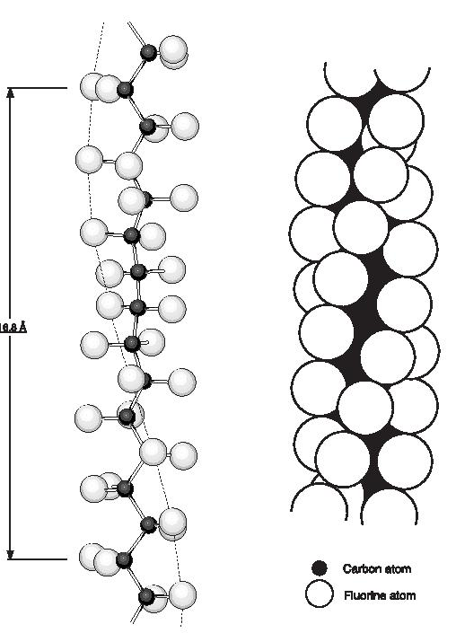
PTFE is a linear chain polymer of great molecular length. The linearity is indicated by an analysis of the infra-red spectrum and by the fact that the powder as produced in the polymerisation reaction is very highly crystalline, with crystalline weight fractions of 0.90 to 0.95 being indicated by density, infra-red and X-ray diffraction measurements. Energy considerations also suggest that branching by chain transfer is unlikely. The crystal structure and chain conformation have been discussed by Bunn and Howells and later by others. The crystalline melting point of sintered PTFE is about 327°C (620°F) and of unsintered material 332-346°C (630-655°F) but there are two reversible first order transitions at lower temperatures,19°C and 30°C (66°F and 86°F), which together involve a 1% change in density. Three crystalline phases are observed at atmospheric pressure: phase I (< 19°C; 66°F), phase ll (19-30°C; 6686°F) and phase lll ( >30°C; 86°F). Below the 19°C (66°F) transition (phase l), the chain repeat distance is 16.8 Å and the CF2 groups are equally spaced along the chain which is twisted to form a helix on which successive carbon atoms lie, thirteen carbon atoms being involved in a twist of 180°, (Figure 1). Between 19 and 30°C (66 and 86°F) (phase ll) the repeat distance increases to 19.5 Å corresponding to a twist of 15 carbon atoms in 180°. Above 30°C (86°F), (phase lll), further disorder sets in and although the molecular conformation prevailing at lower temperatures is maintained, the chains are displaced or rotated along their long axes by variable amounts which increase as the temperature is raised further. The reason for the helical structure is the necessity to accommodate the large fluorine atoms (van der Waals radius 1.35 Å). The rotation at each chain bond, with the slight opening up of the bond angles to 116°, relieves the overcrowding and permits the shortest F-F distance to be 2.7 Å. Further studies by various authors have examined the effect of pressure on the room temperature transitions and the melting point. A study of pressures above-atmospheric revealed a 2% increase in density below 19°C (66°F). This fourth crystalline phase has been labelled phase lll by Weir. A triple point exists at about 70°C (158°F) and 4.5 kilobars. The heats of transition were also determined by Yasuda and Araki; dilatometric and calorimetric studies have in addition been reported by other workers.
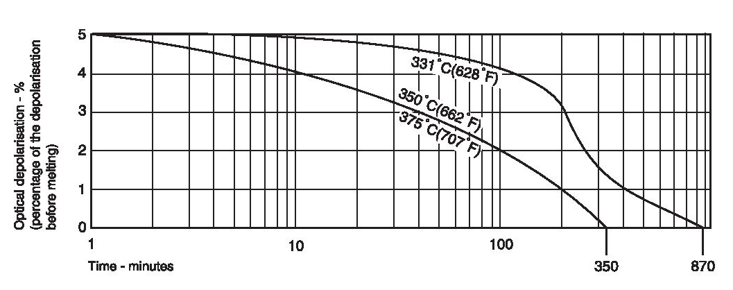
PTFE has a crystalline melting point at atmospheric pressure of about 332-346°C (630-655°F) for unsintered and about 327°C (620°F) for sintered material. The heat of melting has been estimated by Lupton as about 685 cal/mole of CF2 groups and leads to an estimate of the entropy of melting of 1.14 cal/degK mole. This value is low by comparison with polyethylene (2.29 cal/degK mole) and arises from the fact that the stiff long molecules retain a good deal of side-by-side order in the melt. Indeed, if the depolarisation of light is used to detect the course of melting, a finite amount of depolarisation is observed to remain above the melting point (Figure 2). The decay of this residual depolarisation is sensitive to molecular weight, time and temperature. Bunn has ascribed the high melting point to the rigidity of the fluorocarbon chain, small rotations being hindered by the slightly overcrowded fluorine atoms.
The crystallinity and texture of polytetrafluoroethylene have received a good deal of study. Estimations of the degree of crystallinity have been made by X-ray, infra-red and density methods. For 100% crystalline PTFE relative densities of 2.347 at 0°C (32°F) and 2.302 at 25°C (77°F) can be calculated from the X-ray crystallographic data. The density decrease of about 2% between these temperatures includes the decrease of about 1% arising from the transition at 19°C (66°F). The relative density of amorphous PTFE is not affected by this transition and values around 2.00 are obtained by measuring the density at room temperature (preferably 23°C; 73°F) for a number of samples of varying crystallinity, and then extrapolating to zero crystallinity. If the degree of crystallinity is estimated as a result of Xray or infra-red methods it is then possible to calculate a theoretical density. Differences between this theoretical density and the experimentally measured value can be used to assess the void content of a sample. Neither the X-ray nor the infra-red method measures an absolute crystallinity. Each measures ‘disorder’ by a different criterion and, in addition to this, each is subject to purely instrumental limitations, so that even for one of the methods the same value would not necessarily be determined on two different instruments. Tests show the degree of crystallinity measured by the infra-red method is systematically higher than the X-ray crystallinity, the discrepancy being of the order of 5% at 90% increasing to 10% at 50%. For instance, the crystallinities estimated by the X-ray method range from about 90% for unsintered material, 75% for fused and slowly cooled material, to 50% for fused and rapidly quenched samples. The initial high crystallinity and melting point can never be completely recovered after fusion because of the complete reorganisation of the molecular arrangement upon sintering. Crystallisation from the melt in bulk produces long bands which can be seen both in fracture surfaces produced by breakage at liquid nitrogen temperatures, and in sections of the material when viewed microscopically in polarised light. Their dimensions vary from 100 µ m x 1 µ m to 10 µ m x 0.2 µ m depending on the crystallisation conditions and/or molecular weight, the band width being inversely related to molecular weight. The bands show fine parallel striations perpendicular to the band length and it is thought that the bands are the broken edges of thick lamellar crystals. The interpretation of the striations is still uncertain and remains a subject for further investigation. Birefringence measurements show the molecules to lie perpendicular to the bands and since the average length of the molecules is greater than the band thickness chain folding is implied. As the fusion temperature is raised or a lower molecular weight polymer is used (both of which tend to reduce the persistence of order in the melt) the band growths become irregular and tend to agglomerate into spherulitic structures. The use of very high fusion temperatures of around 450°C (842°F) results in well formed spherulites, presumably due to molecular weight reduction as a consequence of thermal degradation. Speerschneider and Li have investigated the role of the large bands in uniaxial deformation and have shown that distortion of the bands occurs at low temperatures.
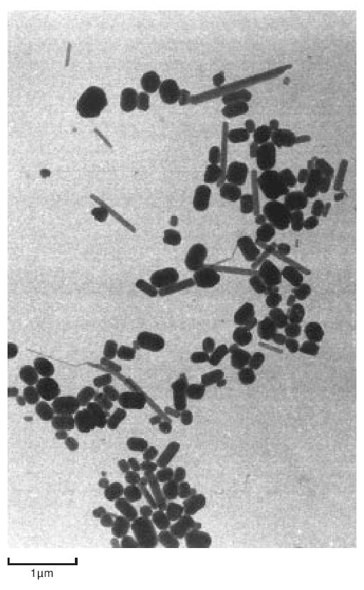
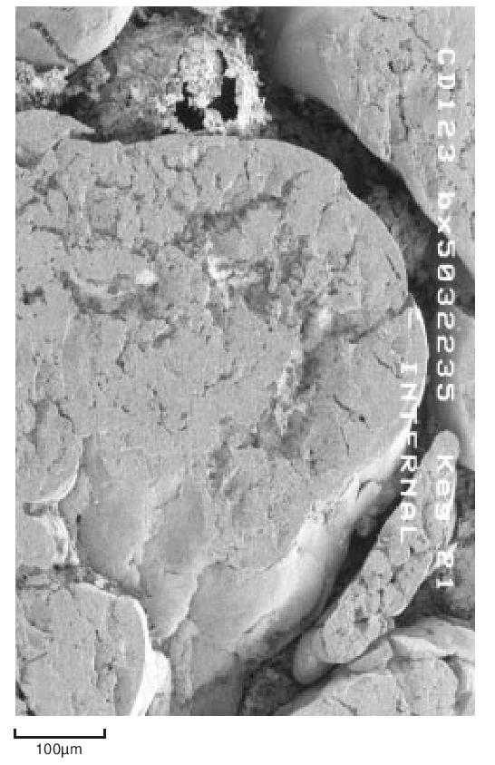
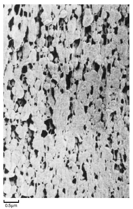
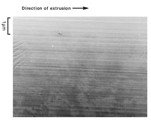
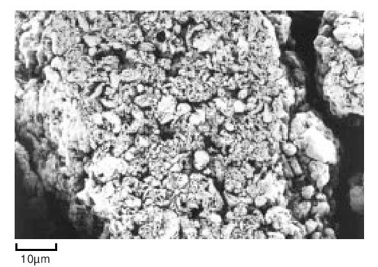
The particles of polymer produced in the dispersion polymerisation process are of the order of 0.2 µ m in size, whilst those from a granular polymerisation are hundreds of µ m in size, built up from smaller particles. They are both highly crystalline - about 90 to 95%. The dispersion particles can be studied directly in a conventional transmission electron microscope, providing the electron intensity is kept low. On raising the electron beam intensity the particles change rapidly in appearance to become transparent with a crumpled texture. At this stage the crystallinity has disappeared and the ‘particles’ probably consist of a shell of carbon. Electron diffraction patterns and dark field micrographs suggest that the particles are composed of a pile of small single crystals with the molecular axis along the axis of the brick-shaped particles. The particles also appear to have a striated surface structure generally parallel to the long axis. A replica of some dispersion particles is shown in Figure 3. During coagulation, the dispersion particles aggregate to form a larger particle, made up of a loose structure of agglomerates of the primary particles (Figure 4). During cold, lubricated extrusion the agglomerated particles are highly distorted, with their primary particles becoming aligned and also drawn into fibrous material. This effect is illustrated in Figure 5. If an extrudate such as that depicted in Figure 5 is sintered and cooled slowly the extrudate will appear as in Figure 6. In Figure 6 the direction of extrusion was from left to right.
During the early stages of polymerisation granular particles form as aggregates of smaller particles. This process continues and large irregular fibrous structures are produced. This material is then modified mechanically to reduce it to the familiar form suitable for processing. For example, Figure 7 shows the structure of a fine particle granular powder.
When PTFE is moulded the basis of the process is that the polymer powder is preformed and then sintered. It is therefore not surprising that mouldings can be produced which contain microscopic voids and fissures arising from the porous nature of the unsintered particles and the molecular re-arrangement caused by sintering. Correct choice of polymer grade and careful use of fabrication techniques will help to minimise the formation of voids. The homogeneity of the final moulding depends a great deal on the compressibility of the particles and their surface structure.
In this respect the behaviour of the particles closely resembles that of powdered metals. Softer particles (generally more porous ones) compact more easily than harder ones and will ‘flow’ more easily to fill interparticulate voids. This leads to a higher ‘green’ strength (of the unsintered preform) and in turn to a higher sintered strength. As with powdered metals the strength both of the preform and of the final sintered moulding depends upon the mean particle size, with finer particles giving higher strengths. According to
Rhines as reported by Goetzel the important factors affecting powdered metals are the number of particle-to-particle contacts and their area. Experiments suggest that, even where no voids exist, variations in internal pressure within a preform result in variations in crystallite size presumably due to the variations in melting point with pressure, for which McGeer and Duus have given the relationship:
Tm = a + bP
Where
T = °K,
P = atmospheres,
a = 597°K and
b = 0.154°C/atm
so that 16 MN/m2 (160 kgf/cm2; 1 tonf/in2) difference in internal pressure can lead to a melting point difference of the order of 25°C (45°F). Such variations in internal pressure will result either from poor packing of the powder in the mould due to poor powder flow properties or from a lack of compressibility in the individual particles. The variation in crystallite size resulting from poor packing leads to variation in translucency from area to area and lack of compressibility gives an overall white and opaque appearance in thin machined sections such as 0.25mm (0.01 inch) skived tape.