
The addition of fillers in PTFE have marked effect on electrical Properties of filled PTFE products.
Although the primary objective in the development of Fluon® grades has generally been to produce materials with a range of mechanical properties, the addition of fillers does have a marked effect on the electrical properties as well. In particular, graphite - and carbon filled compounds may have a relatively high conductivity, which can assist the dissipation of static charges in applications where these are a problem. Filled PTFE is a mixture of materials, and voids - no matter how small - are always present: as with all porous materials, the properties are dependent on the nature of the environment and of any inadvertent contamination. The electrical properties are no exception and are markedly dependent on the environmental humidity. The spillage of conducting liquids, electrolytes and greases on Fluon® grades can affect the properties of the material even in otherwise dry conditions. To some extent porosity (and therefore the effects of humidity and spillage) is dependent upon the method of fabrication, but even in a relatively non-porous part, the surface is liable to be absorbent.
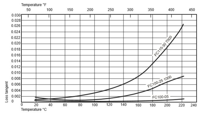
Under dry conditions, the glass-filled grades are excellent electrical insulating materials over a wide range of temperature. Their insulating properties deteriorate with increasing humidity, but even at 95% r.h. the properties are comparable with those of plasticised PVC and of some thermosetting compounds commonly used for insulation. Tables 5, 6 and 7 give values of loss tangent, permittivity and volume and surface resistivities, measured at two levels of humidity, for Glass Filled PTFE grades. The effect of temperature on the loss tangent of some glass-filled grades is shown in Figure 29. The level of dielectric loss tends to increase as glass content increases. However, the mechanisms giving rise to dielectric behaviour of filled materials are complicated, and in general it must be assumed that these materials will exhibit Maxwell-Wagner loss processes of relatively large amplitude at low frequencies (log10 frequency < 0) in the ‘dry’ state, moving progressively to higher frequencies with increasing moisture content. Rudner reports on, but does not interpret, the properties of PTFE filled with titanium dioxide using samples that had been kept at a constant low humidity with silica gel crystals present to absorb moisture. It is suspected that these losses are due to a similar mechanism.
No grade of filled PTFE is a good conductor when compared with, for example, copper or aluminium. However, some have sufficiently low volume and surface resistivities to be considered for use in antistatic applications: see Table 8.
Notes:
Form of specimen: 5 cm (2 inch) diameter disc of skived tape approx.1mm thick (0.04 inch).
Electrode system: No electrodes, 3-terminal fully shielded system.
Test apparatus: General Radio Capacitance Measuring Assembly, type 1620A.
Electric stress: Up to 120 V / mm (3 V / 0.001 inch).
Field direction: Perpendicular to the plane of the sample.
Relative humidity: Dried for 150 h at 0,1 mm Hg at 116°C (241°F).
Accuracy of test result: Estimated to be ± 5%.
| ‘Dry’† | After 9 weeks at 95% r.h. | |||||
|---|---|---|---|---|---|---|
| 103 Hz | 104 Hz | 103 Hz | 104 Hz | 105 Hz | 106 Hz | |
| Unfilled PTFE | 0.0001 | 0.0001 | 0.0001 | 0.0001 | 0.0001 | 0.0001 |
| 5% Glass Filled PTFE | 0.00033 | 0.00032 | 0.14 | 0.122 | 0.058 | 0.0126 |
| 15% Glass Filled PTFE | 0.00065 | 0.00063 | 0.32 | 0.36 | 0.275 | 0.068 |
| 25% Glass Filled PTFE | 0 00107 | 0 00097 | 0.39 | 0.28 | 0.225 | 0.062 |
† Dried for 150h at 0.1mm Hg at 116°C (241°F).
Note: Samples were skived from tape 1.0mm thick veneered (0.04 inch) from blocks preformed at 700 kgf/cm2; 10 000 Ibf / in2 freely sintered for 1 ½ hours at 380°C (716°F) and cooled at approximately 30°C per hour (54°F per hour).
| Ambient humidity | 95% r.h. | |
|---|---|---|
| Unfilled PTFE | 2.02-2.09†† | 2.02-2.09†† |
| 15% Glass Filled PTFE | 2.2-2.5 | 2.2-2.5 |
| 25% Glass Filled PTFE | 2.2-2.5 | 2.2-2.5 |
†† Depending on density
Table 7. Volume and surface resistivity| Volume resistivity(1) (ohm cm) | Surface resistivity(2) (ohm ) | ||
|---|---|---|---|
| Dry(3) | Ambient humidity | 95% r.h. | |
| Unfilled PTFE | >1 x 10¹⁸ | 1017 | - |
| 15% Glass Filled PTFE | >2 x 10¹⁵ | 1015 | 1015 |
| 25% Glass Filled PTFE | >2 x 10¹⁵ | 1015 | 1015 |
Notes :
(1) Measured on discs of skived tape approx. 50.8mm (2 inch) in diameter and 10mm (0.04 inch) thick, using evaporated aluminium electrodes. 1 min. value: 120 V / mm (3 V / 0.001 inch).
(2) 1 min. value at equilibrium with the environment.
(3) Dried for 150 h at 0.1mm Hg at 116°C (241°F).
| Filler(1) by weight % |
Volume resistivity(2) (ohm cm) |
Surface resistivity(3) (ohm) |
|
|---|---|---|---|
| 33% Coke Filled PTFE | 33% | 102 | 104 |
| 25% Coke Filled PTFE | 25% | 104 | 107 |
| 63% Bronze+Graphite Filled PTFE | 63% | 104 | 104 |
| 15% Graphite Filled PTFE | 15% | 106 | 1014 |
| 60% Bronze Filled PTFE | 60% | 107 | 109 |
Notes :
(1 ) Filler % by weight, the remainder being PTFE.
(2) Volume resistivity measured at 23°C (73°F) and 50% r.h. on tape specimens 0.25 to 1.0mm (0.01 to 0.04 inch) thick clamped between disc brass electrodes. The values given are an indication only and may vary widely with fabrication methods.
(3) Surface resistivity measured at 23°C (73°) and 50% r.h. on tape specimens 0.25 to 1.0mm (0.01 to 0.04 inch) thick using disc and ring brass electrodes applied by pressure only. No backing guard electrode used. With some materials the measured surface resistivity is very high even when the volume resistivity is low. This is probably because the veneering method used to prepare tape specimens may have tended to smear a fine PTFE layer on the surface.