
Due to non-polar nature of Virgin PTFE, the dielectric properties, DC conductance behavior is ideal for High voltage Electric applications.
It has been known since 1946 that because of its non-polar nature, the dielectric properties of PTFE were of an ideal character. In 1953 a careful study by Ehrlich in the USA showed that the fall in permittivity from 2.0 to 1.8 in the temperature range 24 to 314°C (75 to 597°F) could be accounted for entirely in terms of density changes by the Clausius-Mossotti formula. No changes of permittivity with frequency were detected and scarcely resolved loss angle† values less than 200 µ radians were recorded.
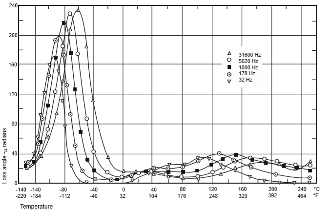
In 1955 Mikhailov and co-workers in the USSR found a loss peak in the -80 to -40°C (-112 to -40°F) range at audio and radio frequencies which was correlated in its temperature / frequency location with dynamic mechanical loss behaviour. From studies of the effect of changes of crystallinity by quenching and slow cooling they concluded that the relaxation losses were attributable to amorphous regions of the polymer. In 1959 Krum and Muller (of Marburg) reported higher dielectric loss values than those found by earlier workers and found more detailed correlation with mechanical properties and effects of crystallinity changes. Eby and Sinnott in the USA have suggested, however, that these higher loss values must be due to polar impurities.
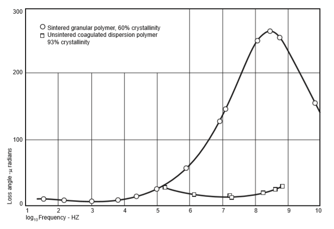
The results of measurement done on behalf of AG Fluoropolymers are presented in Figure 18 where the variation of the loss angle with temperature is given for the range -140 to +240°C (-220 to +464°F) and in Figure 19 as loss angle versus frequency at room temperature. These data, which were obtained using the experimental techniques described in the next column of this page, confirm and extend the findings of Ehrlich and Mikhailov and support Eby and Sinnott’s contention that Krum and Müller’s higher loss values must be due to polar impurities.
The dielectric loss of PTFE is sufficiently low to allow the permittivity to be calculated with an accuracy of better than 0.5% using the Clausius-Mossotti formula:
∈ - 1 / ∈ + 2 = Kd.
where
∈ = permittivity
d = relative density
K = constant, 0.119
From which it can been seen that:
∈ = (1 + 2 Kd) / (1 - Kd)
thus, at a relative density of 2.174 the permittivity is 2.05
† Loss angle in µ radians is very nearly equal to loss tangent (tan δ) x l06, ie 100 µ radians = loss tangent of 0.0001)
Measurements of permittivity and dielectric loss in the audio frequency range (178 Hz - 31.6 kHz) were made using a fully-shielded, three-terminal conjugate Schering bridge; a resonance substitution method, based on that published by Hartshorn and Ward but suitably modified to give a higher resolution, was used for the radio frequency region (105-108 Hz). A modified version of the re-entrant cavity resonator method of Parry was used for the 108 - 109 Hz range; an H01 cavity resonator was used at 9 x 10⁹ Hz: this made use of the Bleaney, Loubser and Penrose method of avoiding unwanted modes.
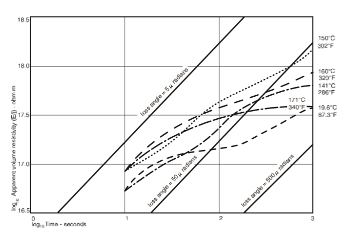
In attempting to study the d.c. conduction behaviour of PTFE, the current measured was that which occurs after the application of a d.c. voltage step. In Figure 20 the results for a typical sintered sample, using evaporated gold electrodes, are expressed as log (apparent volume resistivity) as a function of time of polarisation. It will be seen that steady state conduction was not established clearly in the time of the experiments (which was 15 minutes). On the diagram are shown lines of constant loss angle which can be calculated by means of a Fourier transform assuming a constant permittivity of 2.0. The short time values are consistent with the low frequency values (= 20 µ radians) measured by a.c. methods. In fact it is considered that such d.c. step response results are equivalent to a low frequency extension of the a.c. frequency range. The apparent resistivity is to be thought of as a very low frequency relaxation loss phenomenon rather than a steady state charge transport phenomenon, although the onset of conduction may be apparent above 160°C (320°F).
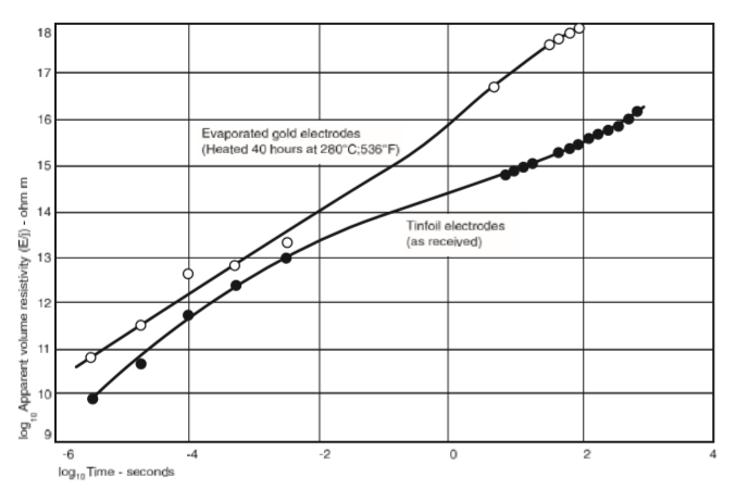
Figure 21 shows that such currents may be removed by heat treatment in the presence of electrodes; apparent resistivity values of > 1018 ohm m have been obtained from such experiments without showing evidence of steady state conduction. However, much lower values are often obtained if unsatisfactory electrodes are used or if temperature stability or polarising voltage stability are not good enough to exclude
V dC / dT or C dV / dT terms for the current.
With regard to high voltage applications it has been known for a long time that in the presence of surface discharges failure occurs by erosion, as PTFE is a nontracking material. Parr and Scarisbrick have compared the behaviour of a wide range of polymeric insulators by the IEE tracking test using electrolyte, and by an ASTM dust-fog test (D21 32-62T). They found that PTFE was one of the erosion class which showed a long life, i.e. >1000 hours in the dust-fog test. Thus PTFE has useful surface characteristics for exploitation in outdoor applications. For bulk insulation high quality fabrication will be required in order to produce structures with the very low level of porosity and internal voiding demanded by high voltage applications. Tests by means of electronic discharge detectors can be made to ensure freedom from the damaging discharges which may occur in voids. Alternatively it is possible to reduce the discharges by impregnating the PTFE with dielectric liquids or with a high pressure gas so as to fill, at least partially, any voids in the polymer. In consequence, values for dielectric strength obtained from tests conducted in oil may be misleadingly high for poorly fabricated PTFE due to impregnation of any voids present by the oil.